How to build an audio reactive individually controlled led strip
Prologue
I'm a big fan of Devon Crawford, a popular DIY youtuber, who creates content on software and hardware DIY projects. I remembered watching his DIY LED Music Visualizer | Real-Time Animations and wished that I could also do it myself.
So today I decided to f*ck it, let's do it. Let's make a audio reactive led strip.
Unfortunately, Devon's DIY involved a frequency to voltage circuit that I had no idea how to build, so I decided to use an open source project, audio-reactive-led-strip, which essentially replaced the frequency to voltage circuit with a out-of-the-box Python code.
Table of Content
Prerequisite
These are the exact prequisite to my experience
- A computer
- Arudino IDE
- Python 2.7 or 3.5
- Virtualenv or Anaconda
- A ESP8266 NodeMCU v3 module
- A breadboard that can fit the module
- A strip of 5V WS2812B individually addressable LED strip. I used 4 meters (read below regarding length)
- A 5V power supply. I used a 15A and it came with a terminal connector (read below regarding current)
- A 470 Ohm resistor
- A 1000 uF capacitor
Explanation
We are going to be using Python to send UDP packets to our ESP8266 module. You can probably replace the ESP8266 with other compatible module that has wifi support. For example, an plain Arudino Uno will not work because it does not have wifi support. You can use serial instead of wifi for this project, but the read and write speed of serial connection via USB is too slow to visualize this project. I'd only recommend serial for really simple visualization. Check out my pull request for example on serial.
It is very important to match the length of your LED strip with the right 5V power supply because the longer your strip, the more power it requires. In order to provide enough power, the 5V power supply has to be able to support a minimum current (amps). For example, I had a 5 meter strip that had a power rating of 18W/meter (you can find this information on the back of your led strip package). Using the power law, P = IV, this means I needed 90W (18*5) from my power supply. However, I only had a 5V power supply rated at 15A, which can only support 75W (5*15). So to make this work, I cut my 5 meter strip into a 4 meter strip, so I only needed 72W (18*4), which will work with my power supply.
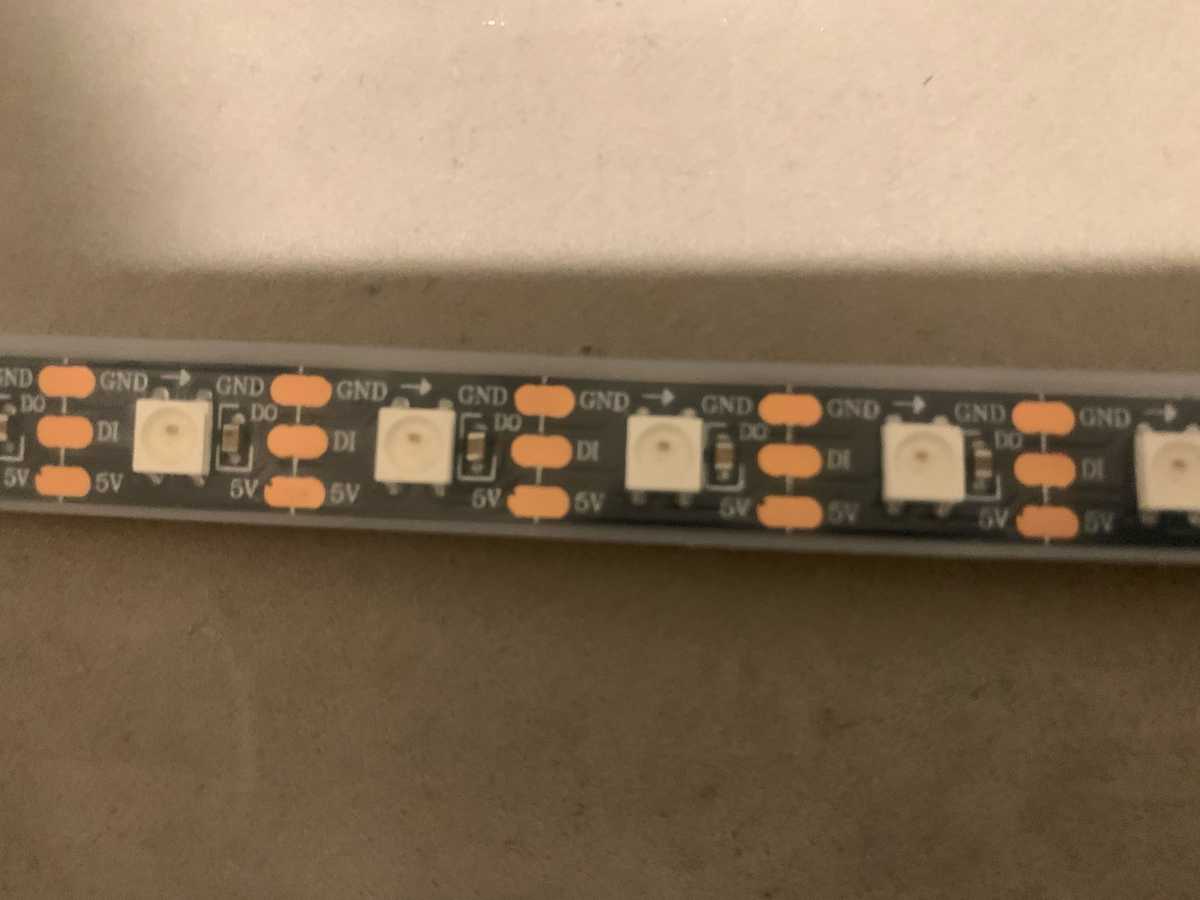
To cut a led strip you want to cut following the white vertical line between the 3 rows of orange-looking thingy.

Software Setup
Follow the README.Hardware Setup
Flush your ESP8266 onto the breadboard. It might take some time for you to wiggle it into the breadboard.
Find the wires of the strip with the white arrow pointing away from you. You should see 2 set of wires:
- set 1: 1 red and 1 black/white
- set 2: 1 red, 1 black/white, and 1 green.
- The red means power, black/white means ground, and green means data-in. The wires on the other direction are for connecting to other strips.
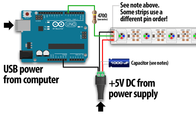
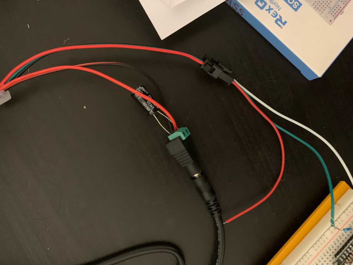
Connect your set 1's power wire to the positive terminal of your power supply's terminal connector and connect set 1's ground wire to the negative terminal. Take your 1000 uF capacitor and connect it across both terminals.
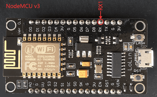
Connect your set 2's data-in wire to a 470 Ohmn resistor and continue to connect to the RX pin on your ESP8266. Connect your set 2's ground wire to the ground of the ESP8266. The other power wire is unused.


Worth noting Theoretically, because the ESP8266 module pins are 3.3V and the data-in wire is 5V. It is recommended to get a logic level converter for dealing with the conversion between 3.3V and 5V. However, my led strip was able to function without the logic level converter, so this is optional.
Testing
Follow README for setting up wifi communication in Python and Arduino IDE.
Connect your ESP8266 to your laptop via microUSB and plug in your power supply. Then upload the Arduino code to your ESP8266.
To test if the LED strip is working, run led.py and make sure you see the a block of LEDs moving across the strip consistently.
Run visualization.py once you have configured your audio input for mic sampling
Enjoy!